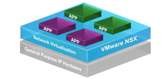
VMware released a free course around Network Virtualization Fundamentals, which maps to the first steps on the ladder for all things NSX. It is also recommended by VMware to take the course before taking on the VCA-NV.
I urge anyone looking into NSX to take this course, you can’t argue with the price after all!!! Secondly, although there are many NSX posts online name, Brad Hedlund has some of the best posts in my opinion.
Check the NSX-Link-O-Rama aswell.
And finally, the NSX Compendium over at Network Inferno
Below are my notes I took whilst going through the course.
The Basics
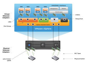
Virtual switch
- Ports organised into port groups
- Uplinks connect virtual switch to physical network
- Connections to support virtual infrastructure
Virtual standard switches – configuration per host, therefore needs to be replicated exactly to all hosts
- Port groups
- VMkernel Ports
- Uplink Ports
- Policies at virtual switch level can be over-ridden at port group level
- VLAN’s set at port group level and VMKernal Port level only
- No support for things like STP, as virtual switches cannot be connected to one another, nor do they learn MAC addresses.
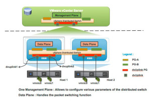
Virtual distributed switch – spans multiple hosts providing centralized management, which makes deployment faster and less room for misconfiguration. As policies are applied at the port group level, rather than the distributed switch level, additional features are available;
- Private VLANs
- NetFlow
- Port Mirroring
- Network I/O Control
The downside to a vDS is the need for the vSphere Enterprise Plus License.
A virtual switch created with no VLANs means the virtual switch itself defines the network segment it is in, i.e by the uplink ports it is in. If multiple VLANs are configured on the uplink ports, the port groups can then be set to which VLAN is used, meaning any Virtual Machine connected to that port group will then be connected to that network segment.
You can automate the creation of the virtual switches, however you are still required to be able to access and change the physical switch and router configuration as needed, or follow the proper change request process. After this is working, you then need to take into consideration the firewall and security device configuration, do these Virtual Machines need protecting by Firewall rules, do they need to talk to devices located on other geographical areas?
Network Virtualisation
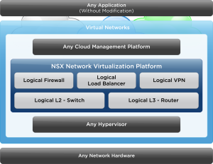
What is network virtualisation? It is more than just creating a switch in which to connect a virtual machine to a physical network, there is also the inclusion of additional services such as, routing, firewalling and load balancing.
In a traditional virtualised network, communications between two VM’s would actually leave the host in which they run on, with NSX deployed, as the communication is between the VM’s and the host, the traffic does not hit the physical network.
By utilizing NSX, management is centralised, and any configurations for VMs such as L2, L3, Firewall and Load Balancing can be moved between the hosts alongside the VMs movements. All without constant reconfiguration of the physical network.
This is achieved by the encapsulation of packets from one VM to another, via the hosts on which they run. A transport VLAN (or VXLAN) is configured to allow for this to take place. This does not stop the virtual networks from allowing communication with the physical network, where by a NSX Layer 2 bridge, or integrations with a 3rd party TOR gateway can be deployed.
NSX allows visibility into the physical network, as it is common that changes are made. A built in tool called “Virtual Distributed Switch Network Health Check” allows the detection of common configuration errors, such as; Mismatch VLAN Trunks; Mismatch MTU Settings; Mismatch Teaming configurations. This information can be then used between vSphere administrators and Network administrators to identify and quickly overcome the issues highlighted.
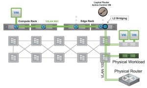
Layer 2 Bridging
Connecting to a physical network topology can be done by using a VXLAN to VLAN Bridge, by using ethernet connectivity between the virtual standard or distributed switch to an uplink into the physical network. This is also known as a Layer 2 bridging. This allows you to;
- Extend virtual services to external devices
- Extend physical servers to virtual machines
- Access to the physical network and security devices
http://i0.wp.com/www.routetocloud.com/wp-content/uploads/2014/10/l2-bridge-topology1.jpg
Layer 2 Bridging is not designed for;
- VXLAN to VXLAN connectivity
- VLAN to VLAN connectivity
Configuring the Bridge, you must have a Distributed Logical Router in your topology. The bridge then uses a dedicated bridge instance (mapped directly to one host), if a Virtual Machine that needs to use the bridge is on a different host, then the VXLAN configuration is used, with the traffic destined for the bridge, moved over the VXLAN to the correct host where the bridge instance lies.
If a bridge to multiple destinations is required, then you can specify a different designated instance for each bridge, which can help with performance issues or concerns about performance.
There are two options for integrating physical workloads into a software overlay.
NSX for vSphere – You can implement a virtual bridge deploying a Distributed Logical Router, as above.
Or use an approved VMware Hardware Vendor device to provide the L2 bridge. This allows physical devices to exist on the same VNI as the Virtual Machines, with a physical switch performing the bridging solution.
NSX Architecture, start with adding a VXLAN, UDP and IP Header to the standard Ethernet frame, this requires an MTU size of 1600 to allow the encapsulation and de-capsulation of this expanded frame.
This En/De-capsulation is performed at the VMKernel on the ESXi host itself. Routing is another function added at this level, meaning the common features of a physical network are starting to be decoupled by the use of NSX.
By allowing these features to take place at the host layer, virtual networks are reproduced easily, and their creation can be automated, with no additional changes to the physical network beyond the changes of MTU.
NSX Architecture
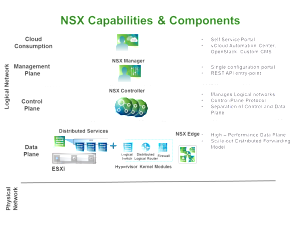
As with a physical network infrastructure, NSX is broken into three components;
- Data Plane
- Control Plane
- Management Plane
The Data Plane is where the actual network traffic flows. Here we have the;
- Distributed Virtual Switch (which is a pre-req for NSX);
- The Virtual Switch, which can span multiple Virtual Distributed Switches;
- The VXLAN VMKernel Port;
- Distributed Logical Router;
- Distributed Logical Firewall.
The NSX manager deploys the above modules into the VMKernel of each host. The NSX Edge Services Gateway is a Virtual Appliance, and implemented for north-south traffic flows, and has its own firewall as well as additional services such as Load Balancing and VPN services.
The Control Plane contains the components that implement the settings and policies used on the data plane. Here we have the following components;
- NSX Logical Router Control virtual machine
- NSX Controller (or Control Cluster)
- User World Agent
The Distributed Firewall is not controlled by the data plane.
The Management Plane provides a single unified user interface too allow the management of both vCenter and NSX within the vSphere Web Client, and therefore contains the following components;
- vCenter
- NSX Manager
- Message Bus Agent
There is a 1 to 1 relationship between vCenter and the NSX Manager.
Above these three planes in the architecture sits the consumption model, which leverages the above planes, this can be either a web portal or self-service portal, where users can select the resources of vSphere and NSX that they need.
The problems NSX solves
Looking at the implications of using NSX to take care of the networking. First off we look at the common problem of routing, on a host if you have two virtual machines, which are connected to two different Virtual Port Groups and subsequently are on two difference subnets, should they send traffic to one another, the traffic will leave the ESXi host, travel along the physical switches in the network and hit the default gateway, which will perform the routing function and then send the packets back on the opposing subnet, via the physical switches to the ESXi Host. This is called Hair-pinning, which is incredibly inefficient .
Using NSX, we can deploy the Distributed Logical Router into the VMKernel of the ESXi hosts, once deployed, you then add logicial interfaces (LIFs) to the DLR, similar to that of adding interfaces to physical router. On the LIFs the network segments are defined (configuring IP addresses and subnets).
Once the DLR is connected to the logical switches, routing can take place in the ESXi Kernel, therefore if we have two machines on different subents on the same host. The traffic between them hits the VMKernel on the ESXi host, and then is routed to the correct machine, without leaving the ESXi host, removing the need for the traffic to hit the physical network infrastructure.
If we take the above scenario, but the VMs are on two different hosts, then without NSX the packet path would be roughly the same, but with the destination be the second host. With NSX, the VMs are connected to a NSX Logical Switch, which is assigned a VXLAN Network ID (VNI) instead of a VLAN. The routing decision is made by the VMKernel on the host, and before the frame leaves the host, the routing decision will already be made to send the traffic over the VXLAN to the other host. The packets will transverse the physical switches to reach the other host, however the physical routing device will not be used to send the packet to the correct destination.
So before NSX, traffic from Virtual Machines would be placed onto the physical network and sent towards physical routers and security devices.
With NSX, the Distributed Logical Routers which are within the VMKernel, provide the routing functions of East to West traffic needed for Virtual Machine connectivity in a data center.
The NSX Edge Services Gateway provides North to South routing of traffic to other internal networks or external networks (Internet). The networks which sit “inside” the internal interface of the NSX Edge Services Gateway are protected the configured firewall rules on the Edge itself.
The NSX Edge allow allows the configuration of routing protocols such as OSPF, IS-IS and BGP, meaning Virtual Machines are connected to the Distributed Logical Router can have their traffic routed to external networks. And on the flip-side, allows external traffic to be routed to the internal network segments.
Taking this further, on a set of hosts, we can deploy two separate DLRs, which can be used to separate tenants within the same private cloud infrastructure. The isolation is maintains by connecting the uplink for each DLR to a unique internal interface on the NSX Edge Services Gateway, which allows the separate tenants access to the external networks.
A NSX Edge Services Gateway is a virtual machine, and is limited to 10 Virtual NICs, at least one virtual NIC is connected to the external network, meaning that there is 9 remaining NICs which can be connected to DLRs (and tenants or internal networks). This Virtual Machine can also be protected by HA within vCenter.
Providing On-Demand Application Deployment
Let’s think about the various network services needed when deployed a mutli-tiered application;
- Configure access ports or trunk links on the physical switch
- Configure routing protocols or static routes
- Add or Modify Firewall rules
- Add or modify rules on the physical load balancer
- Deploy physical devices to provide services that are not available already.
By using the vRealize Automation suite with NSX, you can overcome these challenges, by providing automation to create Logical Switches, Routers, Firewalls, Load Balancers and more. This can be done on the fly as Virtual Machines and Applications are deployed on demand.
NSX Visibility and Troubleshooting
For traffic flow visibility, vSphere supports IPFIX, NetFlow and Flow Monitoring.
For traffic analysis per virtual machine, supported is RSPAN and ERSPAN, for v2v machine traffic, and packet capture and Wireshark plugins are available for the VXLAN.
SNMP and MIBs for all ports used in NSX, are available for Network Inventory and Fault Management.
The usual mutli-level logging, event tracking and auditing is supported and can be sent to syslog servers.
And for traffic transport health, we have the NSX Manager Connectivity Check, mentioned earlier. As well as the NSX Controller Central Command Line Interface, and ESXi Host CLI.
You can also integrate the Log Insight product, which is able to consolidate, visualise and correlate syslog data from multiple components of the SDDC. Which is enhanced further by features such as the ability to create custom real-time dashboards for monitoring and trending.
NSX Gateway
The differentiators from a physical network infrastructure are;
- Logical Switching – Layer 2 over Layer 3 (VXLAN)
- Logical Routing – Between virtual networks
- Logical Firewall – distributed, integrated into VMKernel for high performance
- Logical Load Balancing – done in software, high performance
- Vmware NSX API – a Rest API for integration into any cloud management platform
- Logical VPN – site to site connectivity done in software
- Partner Eco-system – integrating 3rd party vendor devices with NSX
NSX Components
Data Plane
- Virtual Distributed Switch – Required to support NSX Logical Switch
- VTEP – VXLAN Tunnel Endpoint – This is a VMKernel Port used to encapsulate and decapsulate VXLAN traffic.
- Distributed Logical Router – Perform East to West traffic routing
- Distributed Firewall – micro-segmentation
- NSX Edge Services Gateway – provided North to South routing between private and external networks
Control Plane
- NSX Logical Router Control Virtual Machine – Used to distribute routing table updates and logical interface updates to the VMware NSX Controller Cluster
- NSX Controller Cluster – Distributes new routing and switching configurations and updates to the hosts
- User World Agent – Updates the host with Route/Switch information
Management Plane
- vCenter
- NSX Manager – distributes firewall rules to the host
- Message Bus Agent – responsible for transport of these changes
Consumption Model; - vRealize Automation
- vRealize Orchestrator
- REST API supported third party cloud management software
- Self Service Portal
Steps for deploying NSX
- Deploy NSX Manager
- Register NSX Manager with VMware vCenter Server
- Deploy the NSX Controller Cluster
- Prepare the hosts
- Configure and deploy the NSX Edge Services Gateway and configure the network services
- NSX Manager -Manages the logical switches, routers and network service
Central management plane
- 1 to 1 mapping between NSX Manager and vCenter
- Provides management UI and REST API for NSX
- Onto the ESXi Hosts, installs the VXLAN, Distributed Routing, Firewall Kernels and User World Agent
- The configuration of the NSX Controller Cluster is done via REST API
- The configuration of the hosts is done by Message Bus Agent
- Controls the generation of certificates to secure Control Plane communications
- NSX Controller Cluster
Allows the deployment and management of NSX Logical switch/Router information across the hosts in the cluster.
- Instances are clustered for scale out and high availability
- The information about Logicial Switches and Distributed Logical Routers is distributed to all nodes in the cluster to provide load balancing and fault tolerance
- Removes the need for multicast routing, a.k.a protocol independent multicasting (PIM) from physical routers.
- The controller allows the suppression of Address Resolution (ARP) broadcast traffic in the VXLAN networks, as it provides a ARP table
- The VTEPs on the hosts use the provided ARP table reference by default
The NSX Controller Cluster supports five different roles, of which each role needs a master.
- First there is a master role needed for the DLR information and the Logical Switch information.
- Second, two master roles are used for VMware NSX for Multi-Hypervisor.
- One Master for the API Role.
The primary roles in NSX for vSphere, are to support distribution and updating of routing and switching information to all participating hosts. NSX uses a Paxos-based algorithm to determine the master role holder, to guarantee there is just one master for each role.
As many networks can be brought up (using automation) and torn down, think along the lines of the VMware Hands-on-Labs, with labs been built and destroyed each minute, the NSX Controller Cluster is needed to dynamically distribute the workload across all available cluster nodes and provide fault tolerance.
If the resources become dissipated, another node can be added to the controller, and if a node fails, there is zero impact from the applications point of view. In the case of a failed master node, another node will be promoted in its place, if a non-master fails, then the master will redistribute the workload across the remaining nodes.
The deployment of a Controller is done as a virtual appliance, that has 4 vCPUs and 4GB of RAM (modification of settings is not supported). A password for the controller is defined during the deployment of the first node, and this is replicated to all nodes. The Controller nodes must be deployed with the same vCenter Server instance that is mapped to NSX Manager, with a cluster size of a least three Controller nodes is recommended, furthermore is it also recommended that an odd number of NSX Controllers are deployed to avoid a split-brain scenario.
Features of NSX Virtual Switch
Pre-req before creating NSX logical Switch;
- Must be at least one vDS switch
- The host has been prepared with VXLAN
- Distributed Routing
- Distributed Firewall
- Switch Security Module
- Message Bus Agent
Once the above is complete, deploy the NSX Controller instance. The logical router has two components;
- NSX Logical Router Control Virtual Machine
- NSX Logical Router (in the VMKernel)
The Logical Router performs the routing functions in the VMKernel, with the Logical Router Control Virtual Machine performing the following functions;
- Determine functions and interfaces of logical router in the VMKernel
- Perform dynamic routing
- Routing updates by exchanging routes with OSPF peers
- Updates NSX Controller
- Whichever host is running the Logical Router Control Virtual Machine, is the designated bridge instance, meaning this is where Layer 2 VXLAN to VLAN Bridging takes place.
The NSX Edge Service Gateway is a virtual appliance, and does not reside in the VMKernel, providing the following services;
- NAT
- DHCP
- Load Balancing
- VPN
- Edge Firewall
- Dynamic Routing
- OSPF
- IS-IS
- BGP
You can make the ESG high available via the creation of a standby virtual machine.
Components of vSphere Virtual Switch
When creating the Logical Switch, you chose the transport zone which it sits in, meaning the first transport zone must be created before the first virtual switch. This transport zone determines the span of your logical switch across the selected vSphere clusters.
Although you can create multiple transport zones, it is common to have just one. Each logical switch defines a logical network segment, receiving a unique VNI from a pool of VNIs created beforehand, VLANs are not assigned.
Upon the creation of a logical switch, a port group is created within each vDS that is included in the span of the transport zone, connecting the vDS to the logical switch.
Logical switches vSphere features such as, HA & vMotion.
Using the API for provisioning
Using a cloud management system, such as vRealize, virtual networks can be provisioned automatically. The automation system will call NSX API, via the NSX Controller, to do this.
The NSX Controller is a special server created upon the deployment of NSX, that is responsible for creating all the distributed network services and pushing the configuration of them to the ESXi hosts that are to be used in NSX. Via the API, the following network services can be accessed and managed;
- Switches
- Routers
- Firewall Rules
- Load Balancers
- QoS to name but a few
As this is controlled by a particular server, or virtual machine, when a normal production virtual machine moves hosts (i.e during a vMotion event), all of the configured services move with the virtual machine.
VXLAN Deployment
The NSX Manager is responsible for deploying the NSX Controller instances, and preparing the vSphere clusters for VXLAN. The ESXi hosts will provide network information to the NSX Controller using the User World Agent, allowing the NSX Controller to maintain network-state information, which will be cached locally.
At the data plane level, a VTEP (VXLAN Tunnel Endpoint) is created, this is VMKernel Port, for the overlay of VXLAN Tunnel. The VTEPs reside on a VLAN. The VLAN has to be preconfigured on the physical network and span multiple network segments, before the deployment of the VTEP and NSX as a whole.
Once the VTEPs are deployed to the hosts, they become a member of the transport zone, this zone determines the scope of the NSX Logical Switch. The vSphere cluster is added to the transport zone, and adding hosts directly to a zone is not possible.
The VTEP is a network service running in software to provide the encapsulation and de-capsulation to allow layer 2 packets to cross a layer 3 network, therefore spanning datacenter/s.
The transport of packets using a VXLAN in the data centre looks like the following;
- Virtual machine sends a Layer 2 frame
- The source host VTEP adds a VLXAN, UDP, and IP/MAC Headers for encapsulation
- The physical network forwards the frame as a standard IP frame, (it reads the outer frame).
- Once arrived at the destination host VTEP, the packet is de-capsulated, with the additional headers being removed.
- The original Layer 2 will then be delivered to the destination virtual machine.
NSX Load Balancing
Supports one-armed and in-line load balancing
Supports Layer 7 http, https, SSL offloading, and TCP load balancing
The NSX Load Balancer is a virtual machine that can be deployed on demand.
One -armed; deployed with one virtual NIC, utilizes Edge gateway and DLR. It is connected to one of the logical interfaces on the DLR, and a virtual IP address is assigned to the Edge gateway.
In-Line; the load balancing takes place on the edge gateway, which requires two virtual NICs, with the virtual IP sitting on the Edge gateway.
VPN Solutions
- Interoperable IPsec tested with major vendors
- Supports clients on all major OS (Win, OSX, Linux)
- Authentication methods include Active Directory, RSA Secure ID, LDAP and Radius
- Tcp Acceleration
- Encryption – 3DES, AES128, AES256
- AES-NI Hardware Offload
- NAT & Perimeter firewall traversal
- Using with a NSX Load Balancer, can achieve high performance of up to 2Gbps of throughput per tenant.
Micro-Segmentation using NSX
The traditional way of deploying security services, is that at the perimeter, with a firewall device holding a number of rules for all devices, and all devices directing their outbound traffic via this device. This does not however provide security within the boundary between devices on the network, the alternative approach would be to deploy a form of firewall per device for ultimate security, but this is costly and inefficient from a management point of view also.
NSX provides the solution through micro-segmentation, which is taking advantage of the distributed firewall which is found at the hypervisor. Allowing for rules to be created at the Virtual Machine vNIC, as traffic can be inspected before it leaves the Virtual Machine. If the virtual machine is moved to another host, then the rule set will travel with it, and no additional configuration will be needed by an administrator.
Regards
Dean
Follow @saintdle
