Day 4 – Kind of, the course has mostly followed each of my post, however I have kind of mixed and match a few things so they flow better.
Also i’ve found out how to truncate my posts on the homepage, so it says, click here to read more, or something to that effect!As you can imagine, something’s whilst labbing a few things, it can all get muddled.
Just one more quick note, I bought the revision materials from here https://www.ccnpguide.com
I’ve not had a change to look through them properly, but they are well set out and look like a fantastic quick revision guide with all the commands and tidbits of info you need for the exam.
So the topics that will be covered in this one are;
- OSPF Summerization
- OSPF Default Route
- LSA/LSU Types
- Special Areas (Stubby and Not-So-Stubby-Area)
- OSPF Redistribution
- Routing Protocol – Route Filtering
- ACLs for route filtering
- Route-Map for route filtering
- Prefix-List for route filtering
- Policy-Based Routing
- IPv6
- IPv6 with OSPFv3
- IPv6 OSPFv3 Virtual-Link
OSPF Summerization
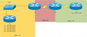
Here’s the topology we worked towards;
Can only summerize on ABR or ASBR (e.g when going from EIGRP into OSPF).
You can use the commands on either an ABR or ASBR;
router ospf [ASN]
area [ID] range [IP address] [Netmask]
OSPF Default Route
Here we are setting out Edge Router (R2) to provide a default route to anything that isn’t inside of the customers network.
ip route 0.0.0.0 0.0.0.0 [Outgoing interface or IP address of next hop]

router ospf [ASN]
default-information originate [Always]
The always commands allows the propagation to other areas;
- Without it, the default route will propagate in Area 0.
- With it, the default route will propagate in Area 0 and 11
LSA/LSU Types
- Router LSAs (DR)
- Network LSAs (DR)
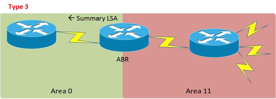
- Summary LSAs (ABR)
- Summary LSAs (ASBR)
- AS External LSA
- Multicast OSPF LSA
- Defined for Not-So-Stubby-Areas
- External Attribute for BGP
- Opaque LSAs (IPv6)
- Opaque LSAs
- Opaque LSAs
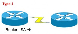
Type 1 = Every OSPF capable router that can generate an LSA within an Area are type 1
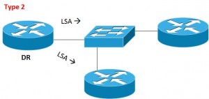
Type 2 = LSA generated by DR router
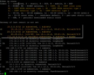
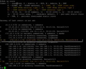
Type 1 and 2 LSAs are Intra-Area LSAs that allow OSPF router to generate “O” routes in the routing table.
See the “Show ip route” output below
Type 3 = AKA ABR Summary LSA, Inter-Area routes, show as “O IA” in the routing table
Type 4 = External routes from ASBR, (i.e EIGRP)
Type 5 = Injected External routes, These generate the following in the routing table
- “O *E1” = Type 1 – AD cost (20) plus route cost
- “O *E2” = Type 2 – AD cost (20) [Default setting]
Type 7 = Special LSA that is used to allow penetration of External Routes when LSA 5 is restricted (Stub area connected to a Not-So-Stubby-Area)
Special Areas (Stubby and Not-So-Stubby-Area)
Eee, what a title, probably set off the search engines of some sort.
See the below table, which details which LSA types are used, and how the routes appear in the routing table;
- Stub = has an ABR
- Not-So-Stubby-Area = has an ASBR
Configuration commands;
router ospf [ASN]
area [Number] stub < Makes this a stub area
area [Number] stub no-summary < Makes this a totally stub area
area [Number] nssa < Makes this a Not-So-Stubby-Area
area [Number] nssa no-summary < Makes this a Totally NSSA
An NSSA ABR does not by default advertise a default route back into the area, using the default-information-originate command does just that.
router ospf [ASN]
area [Number] nssa [no-summary] default-information-originate
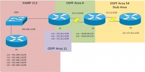
Both routers need to be set as a stub, i.e from the topology in the below (from the OSPF redistribution heading), R2 and R3 would be set as a stub.
OSPF Redistribution
The topology above has been edited from the various other topologies on here, so basically you need to add in the router IPs on networks listed.
When redistributing EIGRP –> OSPF, there are two types
- E1 – this is the AD cost of 20 plus the route to get there
- E2 – this is the AD cost of 20, regardless of the location of the network (this is the default setting)
To configure this redistribution;
router ospf [ASN]
redistribute eigrp [ASN] | [Subnets] | [Metric-type {1/2}]
The first part of the redistribute command distributes the networks in a classfull summary.
Using the “Subnets” command allows classless routes that are not summerized.
The “Metric-type” command specifies the AD distance that will be shown in OSPF
For OSPF –> EIGRP, you need to get the values of the interface to populate EIGRP properly.
Run “Show interface [INT]” on the OSPF interface on the outgoing router of the network, so from above, this would be S0/0/0 which is sat in the 10.1.12.0/25 Network.
Note the values for;
- Bandwidth
- Delay
- Load
- Reliability
- MTU
Then on the Router which is the ASBR, configure as follows;
router eigrp [AS]
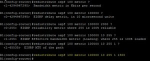
redistribute [Protocol] [ASN] metric [Bandwidth] [Delay] [Reliability] [Load] [MTU]
A real world example would look like
router eigrp 212
redistribute OSPF 100 metric 10000 10 255 1 1500
Routing Protocol – Route Filtering
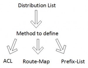
Create Distribution List which is defined via;
- ACL
- Route-Map
- Prefix-List
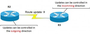
The implementation of these Distribution-List’s are done under the routing processing, which you’ll see further down.
An example would be to look at the Redist. Topology above, here we can exclude at R5 the route 192.168.5.16/30 and 192.168.5.20/30, but permit all other routes to be set to R1.
ACLs for route filtering
These are for use in EIGRP, as it doesn’t work OSPF, and Cisco’s documentation say to use Route-Map for OSPF.
To configure first setup an access-list for the routes you don’t want to appear in other routers tables;
access-list 1 deny 192.168.5.16 0.0.0.3
access-list 1 deny 192.168.5.20 0.0.0.3
access-list 1 permit any
the above can also be achieved by expanding the wildcard as below;
access-list 1 deny 192.168.5.16 0.0.0.7
access-list 1 permit any
Then add this to the routing process;
router eigrp [ASN]
distribute-list [Access-list Number] [Direction (IN/OUT)] [Interface]
So taking the above topology, if we were to set this on R5 it would look like;
router eigrp 212
distribute-list 1 out fa0/0
On this route, the direction is outbound, and the routes are being sent to other routes.
Alternatively we could block it on R1, to stop it appearing to the OSPF network, but any other Routers in the EIGRP area, i.e. connected to the switch, would still receive the routes.
The configuration on R1 would look like;
router eigrp 212
distribute-list 1 in fa0/0
Route-Map for route filtering
Route Maps are setup by;
- Defining the traffic by an ACL
- Creating a route-map (this will impose the action)
A route-map allows you to be more granular with your controller of routes. So you could define a network in your ACL, then have a route map which says anything but what is in this ACL is denied.
So lets have a look at the configuration
     Config#access-list [No] [Action] [Network] [Wildcard]
     Config#route-map [Name] [Action] [Sequence No]
(route-map)#match [value selection] [secondary selection] [ACL No]
OK, so with this there is a lot of values, that you need to have a good play around with so you understand them yourself, but heres a working example;
     Config#access-list 5 permit 192.168.5.16 0.0.0.7
     Config#route-map deny-5.16 deny 10
(route-map)#match ip address 5
(route-map)#exit
     Config#route-map deny-5.16 permit 20
So now we need to add this into the routing protocol, as above this is recommended for OSPF so this is how we’ll do it, but you can adjust it for EIGRP;
router ospf [ASN]
distribute-list route-map [Name] [Direction] [Interface]
And here’s a working example as from the same topology;
route ospf 100
distribute-list route-map deny-5.16 in fa0/0
Note: you cannot set route-map to the outside direction for OSPF, as all routers need an identical LSDB
Prefix-List for route filtering
Create a Prefix List containing IP address and Mask and apply to routing process.
ip prefix-list [Name] Sequence [No] [Action] [Network] [Mask]
ip prefix-list [Name] Sequence [No] [Network] [Greater/Less Than] [Mask]

router [protocol] [ASN]
distribute-list prefix [Name] [Direction] [Interface]
With Prefix-Lists you can specify the masks using CIDR. Ok so let’s look at a working example.
ip prefix-list Block-5.16 sequence 10 Deny 192.168.5.16/30
ip prefix-list Block-5.16 sequence 20 permit 0.0.0.0/0 less 32
router ospf 100
distribute-list prefix Block-5.16 in s0/0/
Adding the second line allows all the other routes to appear.
Policy-Based Routing
These can be set to take place before or after the routing table.
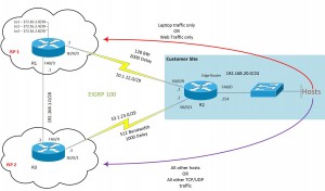
So using the above topology, we are going to send date from a laptop (192.168.1.20) via ISP 1, and all other hosts via ISP 2.
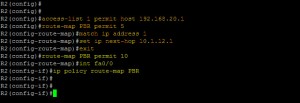
So on Router 2, If we wanted to take all traffic from one host and send it via a particular route, and all other traffic via an alternative, the configuration would look something like the below.
#access-list 1 permit host 192.168.20.1
#route-map PBR permit 5
(route-map)#match ip address 1
(route-map)#set ip next-hop 10.1.12.1
(route-map)#exit
#route PBR permit 10
#int fa0/0
(config-line)#ip policy route-map PBR
If you wanted to do this for certain traffic, for example HTTP traffic;
#access-list 100 permit tcp any any eq www
#route-map PBR permit 5
(route-map)#match ip address 100
IPv6
Ooo it’s the hated one!!! But we need to know it for the CCNP old and new.
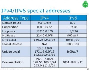
Here’s a quick table someone posted on twitter for the reserved IPv6 address ranges.
To enable, the Router config is;
#ipv6 unicast-routing
- Running IPv4 + IPv6 together is called Dual-Stack.
To enable on a switch;
sdm prefer dual-ipv4-and-ipv6 defaul
If you run IPv4 on one network, and IPv6 on another, you need to create a tunnel;
- 6to4 Manual
- 6to4 Auto
- ISATAP
- Teredo
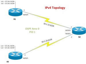
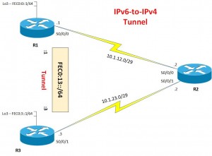
So below is the IPv4 Topology of the network;
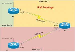
And now here is the IPv6 Topology of the network;
So here we can set both IPv4 and IPv6 address on the same interface, which allows the two topologies to be combined.
IPv6 with OSPFv3
So lets look at the start of the config to achive the IPv6 OSPF topology;
ipv6 unicast-routing
interface [interface]
ipv6 address [address and mask]
ipv6 ospf [PID] area [area id]
Here you can see that you link the OSPF IPv6 process to the interface directly.
Here is a working configuration;
#ipv6 unicast-routing
#interface s0/0/0
(config-line)#ipv6 address FEC0:12::1/64
(config-line)#ipv6 ospf 101 area 11
Ok so the next thing we need to do is change the OSPF router ID under IPv6, this is because the ID actually mimics a IPv4 address, so it can become a bit confusing.
ipv6 router ospf 101
router-id 1.1.1.1
exit
exit
clear ipv6 ospf process
By issuing the clear command, this resets OSPF meaning it uses the new RID.
IPv6 OSPFv3 Virtual-Link
OK, so most of you by now should have realised any issue with the above topology, the fact that Area 54 doesn’t “touch” area 0, therefore we need to create a Virtual-Link.
On Router 1;
ipv6 router ospf 101
area 11 virtual link [RID of R2]
On Router 2;
ipv6 router ospf 102
area 11 virtual link [RID of R1]
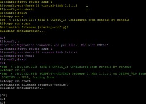
So below, in Yellow we have Router 1 config, in Purple, we have Router 2 config, and finally in Green we have the OSPF Adjancey forming.
6to4 Manual Tunnel
Ok to make the above topology from the previous ones, remove the IPv6 addressing off Router 2, and add the IPv4 addresses, on the Serial links on R1 and R3, do the same.
To create the tunnel, on R1 and R3 enter the following config;
interface tunnel [Number]
ipv6 address [Address]
tunnel source [interface]
tunnel destination [IPv4 address of dest. router]
tunnel mode ipv6ip
no shut
Here is a working configuration;
R1(config)#interface tunnel 0
R1(config-line)#ipv6 address FEC0:13::1/64
R1(config-line)#tunnel source s0/0/0
R1(config-line)#tunnel destination 10.1.23.3
R1(config-line)#tunnel mode ipv6ip
R1(config-line)no shut

R3(config)#interface tunnel 0
R3(config-line)#ipv6 address FEC0:13::1/64
R3(config-line)#tunnel source s0/0/1
R3(config-line)#tunnel destination 10.1.12.1
R3(config-line)#tunnel mode ipv6ip
R3(config-line)no shut
OSPF over a IPv6 Tunnel
Put loopback of R1 into Area 0. Put Tunnel into Area 0
Configuration;
interface [interface]
ipv6 ospf 101 area 0
6to4 Auto Tunnel (Point-to-Multipoint)
These types of tunnels have a reserved IPv6 range of 2002::/16.
The Tunnel Address is made from;
16 Bit Reserved + 32 Bit IP address of Source + 16 Bit Subnet of Tunnel + IPv6 Host.
Yeah, mouthful! Ok, so let’s take the tunnel we will be creating from the above topology. At first it will look like this;
- Router 1 – 2002:10.1.12.1:13:1
We need to change the IPv4 address in Red into Hexadecimal, so it will become;
- Router 1 – 2002:0A01:0C01:13::1/64
And finally here’s Router 3 – 2002:0A01:1703:13::1/64
To configure for R1, and then adapt for the same side to R3;
interface tunnel 0
ipv6 address 2002:0a01:0c01:13:1/64
tunnel source s0/0/0
tunnel mode ipv6ip 6to4
no shut
You then need to configure static routes!!!
ipv6 route 2002::/16 tunnel 0
ipv6 route FEC0:3::/64 2002:0A01:1703:13::3
I’ve highlighted the changes in config in red for the 6to4 Auto compared to 6to4 Manual.
As you can see its not so Auto! if anything its more of a pain!!!!
ISATAP (Point to Multipoint)
This needs to be setup within the site, and is not routable. Uses the IPv6 EUI address strategy.
Configuration for Router 1 then adapt for Router 3;
interface tunnel 0
ipv6 address FEC0:13::/64 EUI-64
ipv6 tunnel source s0/0/0
ipv6 tunnel mode ipv6ip isatap
no shut
exit
Once again I have highlighted the configuration setting changes from the other options in Red.
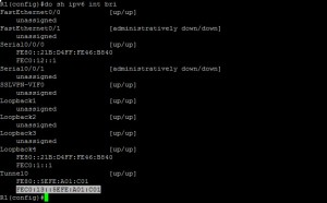
You need to add static routes once again, however as you’ve specified “EUI-64” in the config, you need to get the IPv6 address that’s being configured, of which you can do this using;
Show ipv6 interface brief
Then you need to add the route
ipv6 route [destination]
Here’s a working config;
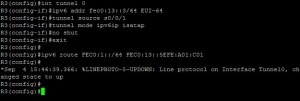
ipv6 route FEC0:3::/64 FEC0:13::5EFE:0A01:C01
Below you can see working examples of setting up IPv6 ISATAP tunnel.
And that concludes this blog post, what a busy day of training eh???

